A humble twisted wire that connected billions of devices around the world — and still shows no signs of stepping down.
A Brief History
It all started in 1881, when Alexander Graham Bell — yes, the same man who invented the telephone — patented a method of twisting telephone wires together. The problem was straightforward: early telephone lines were run in parallel, and they interfered with each other terribly. Listeners heard noise, fragments of other conversations, and hum from electric lamps. Bell noticed that twisting two wires together dramatically reduced mutual interference.
The physics is elegant: external interference induces the same voltage on both conductors of a pair. The receiver only responds to the difference between them, and the interference cancels out. This principle is called differential signaling, and it is very much alive today.
For decades, twisted pair remained purely a telephone technology. In the 1970s and 80s, with the rise of personal computers and local area networks, engineers began wondering whether the telephone wiring already installed in buildings could carry data. It turned out it could — but standards were needed.
In 1991, the TIA/EIA organization published the first structured cabling standard: TIA-568. It defined cable categories, installation rules, and maximum distances. From that point on, “category” became the central word in every network installer’s vocabulary.
What Is Twisted Pair and Why Is It Twisted
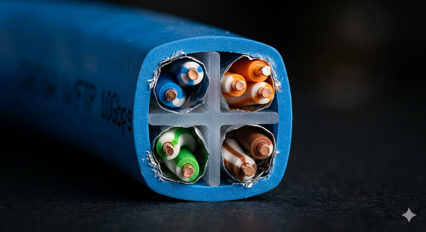
Twisted pair (abbreviated TP) is a cable consisting of one or more pairs of copper conductors twisted together along their entire length.
The twisting serves two key functions:
1. Protection from external interference (EMI) External electromagnetic fields — from motors, fluorescent lights, radio transmitters — induce equal voltages on both wires of a pair. The differential receiver at the far end sees only the difference, which is zero. The interference is cancelled.
2. Protection from mutual interference (crosstalk) A cable contains several pairs. Each pair acts like a small transformer and can induce signals onto neighboring pairs. To minimize this, each pair is twisted at a different twist rate. If all pairs had the same twist rate, they would resonate and amplify mutual interference. Different rates break that resonance.
This is why in a quality Cat5e cable and above, you will notice that the four pairs are twisted differently: one at roughly 1–2 cm per twist, another at 2–3 cm, and so on. The exact values vary by manufacturer and are part of their proprietary know-how.
Cable Construction
A typical twisted pair cable consists of the following layers:
╔════════════════════════════════════╗
║  Outer jacket (PVC / LSZH)         ║
║  ┌────────────────────────────┐    ║
║  │  [Overall shield — if any] │    ║
║  │  ┌────────┐  ┌────────┐    │    ║
║  │  │ Pair 1 │  │ Pair 2 │    │    ║
║  │  │ ══════ │  │ ══════ │    │    ║
║  │  └────────┘  └────────┘    │    ║
║  │  ┌────────┐  ┌────────┐    │    ║
║  │  │ Pair 3 │  │ Pair 4 │    │    ║
║  │  │ ══════ │  │ ══════ │    │    ║
║  │  └────────┘  └────────┘    │    ║
║  └────────────────────────────┘    ║
╚════════════════════════════════════╝
Conductor — typically a copper wire with a diameter of 0.4–0.65 mm. The most common gauges are AWG 24 (0.511 mm) and AWG 23 (0.574 mm). Conductors are either solid or stranded.
Pair insulation — polyethylene or foamed polyethylene. The quality of this insulation determines the dielectric properties and therefore the bandwidth of the cable.
Pair separator — some cables include a cross-shaped polyethylene spline between the pairs to reduce crosstalk. Common in Cat5e and Cat6.
Outer jacket — most often PVC (polyvinyl chloride) for indoor use, or PE (polyethylene) for outdoor installation. In environments with strict fire safety requirements, LSZH (Low Smoke Zero Halogen) compounds are used — these produce minimal smoke and no halogen gases when burned.
Types by Shielding
This is one of the most important classifications, and for years the industry suffered from chaotic and inconsistent naming. In 2002, ISO/IEC 11801 introduced a unified notation — X/YTP — which remains the standard today.
The X/YTP Notation
- X — overall shield for the entire cable:
U(unshielded),F(foil),S(braided screen),SF(braid + foil) - Y — individual pair shield:
U(unshielded),F(foil) - TP — twisted pair
Main Types
| Designation | Old Name | Description | Typical Use |
|---|---|---|---|
| U/UTP | UTP | No shielding whatsoever | Offices, homes, most LANs |
| F/UTP | FTP | Overall foil, pairs unshielded | Industrial zones with interference |
| U/FTP | STP | Each pair foiled, no overall shield | Cat6A, 10G networks |
| F/FTP | SFTP | Each pair foiled + overall foil | Data centers, medical, industrial |
| SF/FTP | — | Each pair foiled + overall foil + braid | Maximum shielding |
Important: Shielded cable requires grounding of the shield at both ends. An ungrounded shield becomes an antenna and makes things worse. A classic beginner’s mistake: install STP cable and forget to ground it.
UTP vs STP: Which to Choose?
U/UTP is the default choice for offices and home networks. Easier to install, cheaper, no need for grounded infrastructure.
Shielded cable belongs in industrial environments, server rooms, and medical facilities where electromagnetic interference levels are significantly higher. Also required for Cat6A and above in certain installations.
Cable Categories
A category (Cat) is a specification that defines the frequency characteristics of a cable — permissible attenuation levels, crosstalk limits, and other parameters. Higher category means stricter manufacturing requirements and better signal quality.
Category Reference Table
| Category | Standard | Bandwidth | Max Speed | Max Length | Notes |
|---|---|---|---|---|---|
| Cat1 | — | < 1 MHz | — | — | Voice, ISDN. Not formally standardized by TIA |
| Cat2 | — | 4 MHz | 4 Mbps | — | Token Ring. Obsolete |
| Cat3 | TIA-568 | 16 MHz | 10 Mbps | 100 m | 10BASE-T Ethernet |
| Cat4 | — | 20 MHz | 16 Mbps | 100 m | 16 Mbps Token Ring |
| Cat5 | TIA-568-A | 100 MHz | 100 Mbps | 100 m | Fast Ethernet. Discontinued |
| Cat5e | TIA-568-B | 100 MHz | 1 Gbps | 100 m | Most common for home and SMB |
| Cat6 | TIA-568-B.2-1 | 250 MHz | 1 Gbps (10G to 55 m) | 100 m | Better crosstalk, often includes spline |
| Cat6A | TIA-568-C.2 | 500 MHz | 10 Gbps | 100 m | Required for 10GBASE-T at full 100 m |
| Cat7 | ISO/IEC 11801 | 600 MHz | 10 Gbps | 100 m | S/FTP, GG45/TERA connectors |
| Cat7A | ISO/IEC 11801 | 1000 MHz | 40 Gbps | 50 m | Niche applications |
| Cat8 | TIA-568-C.2-1 | 2000 MHz | 25/40 Gbps | 30 m | Data centers, server interconnects |
| Cat8.1 | TIA-568-C.2-1 | 2000 MHz | 40 Gbps | 30 m | RJ-45 compatible connector |
| Cat8.2 | ISO/IEC 11801 | 2000 MHz | 40 Gbps | 30 m | TERA/GG45 connector |
Practical Recommendations
Home network or small office: Cat5e is sufficient for gigabit internet and most tasks. Cat6 if you want headroom for the future or have longer runs.
New construction: Install at minimum Cat6A. The cable costs only marginally more, and 10 Gbps will become a standard expectation sooner than you think.
Data centers: Cat6A or Cat8 depending on distances and required speed. At runs under 30 m, Cat8 delivers 40 Gbps.
Interesting fact: Cat5 and Cat5e share the same bandwidth — 100 MHz. The difference lies in stricter crosstalk requirements (NEXT, FEXT, PSNEXT) in Cat5e. It is precisely these tighter specs that enabled Gigabit Ethernet, which uses all four pairs simultaneously in full-duplex.
Speed and Bandwidth
These two terms are frequently confused, so it is worth clarifying.
Bandwidth — the range of frequencies a cable can transmit with acceptable attenuation. Measured in MHz. This is a physical characteristic of the cable.
Data rate — the number of bits per second that a networking standard actually achieves over that cable. It depends not only on the cable but also on the encoding scheme.
For example, 1000BASE-T (Gigabit Ethernet) delivers 1 Gbps over Cat5e (100 MHz) thanks to PAM-5 encoding (5 amplitude levels) and simultaneous use of all four pairs in full duplex. The signal frequency per pair stays within 125 MHz.
10GBASE-T requires Cat6A (500 MHz) because it uses even more complex PAM-16 encoding and is extremely sensitive to crosstalk — hence the far stricter pair shielding requirements in Cat6A.
Factors Affecting Real-World Performance
- Length — attenuation increases with both frequency and distance. The standard segment is 90 m of fixed cabling + 10 m of patch cords = 100 m total.
- Termination quality — a poorly crimped RJ-45 or sloppy patch panel termination destroys the characteristics of even the most expensive cable.
- Temperature — at elevated temperatures, conductor resistance increases and attenuation rises. Critical for outdoor runs and attic installations.
- Bend radius — tight bends alter the twist geometry inside the cable and worsen crosstalk. Minimum bend radius for Cat6A is 4× the cable’s outer diameter.
Conductor Materials
Copper (Cu)
The industry standard. Low resistivity, good solderability, long service life. Cables with pure copper conductors are unmarked or simply labeled Cu.
Copper Clad Aluminum (CCA)
CCA is an aluminum conductor coated with a thin layer of copper. It is roughly 30–50% cheaper than solid copper.
Problems with CCA:
- Aluminum has higher resistivity — more attenuation on longer runs
- Aluminum oxidizes differently — unreliable contacts in connectors over time
- More brittle and less flexible — CCA patch cords are a disaster waiting to happen
- Does not comply with TIA/EIA or ISO standards — CCA cables cannot be legally labeled Cat5e/Cat6 under these specifications
Unfortunately, the market is flooded with cheap CCA cables bearing a “Cat6” label. The check is simple: snap one conductor. Copper bends; aluminum breaks. Alternatively, use a cable tester — CCA will show measurably higher loop resistance.
Advice: For permanent installations (cables sealed inside walls for years) use solid copper only. CCA is a counterfeit product sold under the appearance of a standards-compliant cable.
Standards and Organizations
| Organization | Standards | Region |
|---|---|---|
| TIA (Telecommunications Industry Association) | TIA-568 | USA, North America |
| ISO/IEC | ISO/IEC 11801 | International |
| EN (CENELEC) | EN 50173 | Europe |
| IEEE | 802.3 (Ethernet) | International |
There are minor differences between TIA and ISO/IEC definitions. For instance, Cat6A under TIA and Class EA under ISO/IEC are technically equivalent but not identical specifications. For practical purposes, the difference is negligible.
Applications
Ethernet (Local Area Networks)
The primary application. Ethernet over twisted pair has evolved from 10 Mbps (10BASE-T, 1990s) to 40 Gbps (40GBASE-T, Cat8, 2016). Today, the overwhelming majority of corporate and home networks are built on Cat5e or Cat6.
PoE (Power over Ethernet)
The technology for delivering electrical power alongside data over twisted pair. Standards:
| Standard | Power | Typical Devices |
|---|---|---|
| PoE (802.3af) | 15.4 W | IP cameras, IP phones |
| PoE+ (802.3at) | 30 W | Wi-Fi access points |
| PoE++ (802.3bt) Type 3 | 60 W | TVs, laptops |
| PoE++ (802.3bt) Type 4 | 100 W | Thin clients, video conferencing endpoints |
For PoE++ (60–100 W), Cat6A or higher is recommended — better conductor quality reduces cable heating under load.
Telephony
This is where it all began. Telephone lines — analog, ISDN, DSL — are still wired with Cat3 twisted pair or plain telephone cable.
Industrial Networks
Industrial Ethernet (Profinet, EtherCAT, Modbus TCP) requires specialized industrial twisted pair cable — with reinforced mechanical protection, resistance to oils, UV, and vibration. A distinct niche with its own strict requirements.
Audio and Video
A balun (balanced-unbalanced converter) allows analog audio and video signals to be transmitted over twisted pair across significant distances. In large installations — conference halls, stadiums — this is cheaper than coaxial cabling.
HDBaseT is a standard for transmitting HDMI signals over twisted pair up to 100 m. Requires Cat6 or Cat6A. Widely used in professional AV installations.
Security Systems
IP video surveillance has almost entirely migrated to Ethernet + PoE + twisted pair. Analog CCTV systems also frequently use baluns to carry video over Cat5e.
Smart Buildings and Automation
KNX, BACnet, DALI — building automation protocols that run over twisted pair. While wireless protocols (Zigbee, Z-Wave, Matter) are making inroads in residential settings, wired solutions remain the standard in commercial real estate.
Installation and Termination
Pin Assignment: T568A vs T568B
Two standards exist for wiring an RJ-45 connector:
T568B (most common internationally):
Pin: 1        2       3        4      5         6      7        8
     W-Orange Orange  W-Green  Blue   W-Blue    Green  W-Brown  Brown
T568A (US government standard for new installations):
Pin: 1        2      3         4      5         6       7        8
     W-Green  Green  W-Orange  Blue   W-Blue    Orange  W-Brown  Brown
The rule is simple: both ends of a cable must use the same standard. If one end is T568A and the other is T568B, you have a crossover cable — intended for connecting two computers directly. Modern network cards support Auto-MDIX and will negotiate regardless, but it is better practice not to rely on it.
Installation Rules
- Minimum bend radius: 4× the outer diameter of the cable (slightly more for Cat6A)
- Do not run parallel to power cables closer than 150 mm (UTP) or 50 mm (FTP)
- When crossing power cables, cross at 90 degrees only
- Maximum untwisting at termination: 13 mm for Cat5e, 6 mm for Cat6
- Do not kink the cable; do not overtighten cable ties
Testing
After installation, cable runs should be tested. There are two levels:
Wiremap — basic verification: all 8 conductors are connected correctly, no opens or shorts. A simple pass/fail tester costing a few dollars handles this.
Certification — full testing to standard: attenuation, NEXT, FEXT, PSNEXT, return loss, propagation delay. Requires a certification tester (Fluke DSX, IDEAL, Softing). Mandatory for any installation covered by a manufacturer’s channel warranty.
Common Mistakes
1. Excessive untwisting of pairs When crimping RJ-45 connectors or terminating patch panels, some installers untwist the pairs too far for convenience. The result is degraded crosstalk performance and a failed certification.
2. CCA instead of solid copper Particularly painful in PoE installations — aluminum heats up more, and contact issues emerge within a year or two.
3. Overtightened cable ties Cable ties cinched too tightly deform the internal twist geometry. The result is measurably degraded cable characteristics.
4. Ungrounded shielded cable The shield becomes an antenna and amplifies the very problem it was supposed to solve.
5. Mixing T568A and T568B on the same cable An accidental crossover. Especially dangerous when the installer “can’t remember which scheme they used” at the other end.
6. Ignoring minimum bend radius Most common at corners and at the exit points from cable trays and conduits.
Alternatives and the Future
Fiber Optic
No longer exotic. The cost of SFP modules and multimode fiber has dropped to the point where, in new large offices and data centers, fiber between switches is standard practice. But the “last mile” to the workstation remains twisted pair: patch cords, IP phones, PoE cameras — all of it requires RJ-45.
Wi-Fi 6E and Wi-Fi 7
Wireless technology is encroaching on the office twisted pair market. Wi-Fi 7 theoretically delivers over 40 Gbps per access point. But those access points themselves connect via Cat6A or fiber — so wireless only displaces twisted pair on the final segment.
2.5GBASE-T and 5GBASE-T
An interesting middle ground: IEEE 802.3bz (2016) enables 2.5 Gbps and 5 Gbps over existing Cat5e/Cat6 cable at 100 m. This saves companies that invested in Cat5e infrastructure from having to re-cable just to support faster Wi-Fi uplinks. Now widely adopted in Wi-Fi 6 access points.
Cat8 and Beyond
Cat8 is in real production use in data centers for inter-rack connections at distances up to 30 m. Forty gigabits per second over 30 meters of copper cable is a remarkable result. However, Cat9 or Cat10 have not been announced, and for good reason: above 2 GHz, the physics of copper cable become increasingly problematic, and fiber wins decisively.
Conclusion
Twisted pair is one of the most successful technologies in the history of telecommunications. Over 140 years it has traveled from Bell’s telephone patent to 40-gigabit data center interconnects. It has outlived competitors: coaxial Ethernet (10BASE2, 10BASE5), Token Ring, FDDI — and continues to underpin wired networking worldwide.
The secret to its longevity is simplicity, low cost, and the fact that the physics of differential signaling with interference cancellation turned out to be so effective that it is very hard to beat. Each new generation of engineers only tightens the manufacturing tolerances and complicates the signal encoding — while the core idea remains exactly what Alexander Graham Bell patented in 1881.
Article prepared for a technical audience. Specifications cited in accordance with TIA-568 and ISO/IEC 11801 standards as current at the time of writing.